
- Sourcing CNC machining? The test is not the tolerance printed on a brochure — it is whether the shop can hand you a CMM report for the exact feature you are buying, with the band, the sample size and the study window all named.
- What CNC machining is: a subtractive process — a cutter removes material from a workpiece along a programmed toolpath until the geometry, tolerance and surface finish on the drawing exist.
- Over 100 machines on one floor — Mazak / Brother / Tsugami / Star / Citizen class across 6,800 m², with 50+ 3-axis, 20+ 4-axis, 20+ 5-axis, 25+ lathes, 7+ grinders and 20+ inspection instruments.
- Held tolerances: ±0.003 mm, turning ±0.002 mm, grinding ±0.002 mm, each checked on Hexagon CMMs. Capability is stated per characteristic — Ppk ≥ 1.67 initially and Cpk ≥ 1.33 in production for key and special characteristics (≥ 1.33 general). Each report lists the feature, band, sample size, sigma method and study window.
- Certified under ISO 9001:2015, IATF 16949:2016 (design excluded) and ISO 14001:2015 — Dongguan Zhuohang Ltd is the invoicing entity behind them.
- Order terms: MOQ 1 piece, lead times of roughly 3 / 7 / 30 days depending on complexity.
What is CNC machining?
CNC machining is the subtractive manufacturing of parts on computer-numerically-controlled milling, turning, and grinding equipment. A cutter removes material from a workpiece along a programmed toolpath to produce a part that meets a drawing-defined geometry, tolerance, and surface finish. "CNC" means the tool path is numerically controlled rather than hand-operated.
The rest of this guide turns that definition into a buyer's checklist for this shop — what to verify before you commit, and how the numbers on the drawing actually reach the part.
The discipline separates into milling (the cutter rotates and the workpiece is fed; prismatic geometry), turning (the workpiece rotates and the tool is fed; rotational geometry), and precision grinding / wire EDM (the tightest tolerances on critical features). A plant that produces CNC machined parts end-to-end runs all three.
The output of CNC machining is a part that meets the drawing — geometry, tolerance, surface finish, and material certificate — and is documented to a quality plan (FAI for general work, PPAP for automotive-bound parts, IMDS for material data). That is the answer to "what is CNC machining": a numerically-controlled subtractive process that produces a part to a drawing, with the quality documentation that lets the part enter an assembly.
- DFM before quoting. Every quote ships with a design review that flags internal corners, thin walls, deep pockets, and over-tight tolerances.
- 100+ production machines — 3-axis (50+), 4-axis (20+), 5-axis (20+), 25+ lathes, 7+ grinders across a 6,800 m² facility. ±0.003 mm CNC milling, ±0.002 mm CNC turning; ±0.002 mm grinding, verified on Hexagon CMMs.
- MOQ 1 piece, lead times of roughly 3 / 7 / 30 days depending on complexity.
- ISO 9001 · IATF 16949 · ISO 14001 certified, build-to-print (IATF scope excludes design, Clause 8.3).
What is DFM, and why is it your most overlooked lever?
Design for manufacturability is the discipline of shaping a part so it can be made reliably, quickly, and cheaply with a given set of processes. Most of a machined part's cost is decided before any metal is cut — in the geometry you drew, the tolerance you called out, and the material you selected. A part that needs five setups will always cost more than one that needs two, regardless of who quotes it.
The practical consequence for you is that DFM feedback is worth more than a price cut. Ten percent off a quote is a one-time saving; a design change that removes a setup is a permanent one, repeated on every unit, for the life of the part. That is why a supplier who reviews your drawing before quoting — and tells you what to change — is worth more than a supplier who simply agrees to everything and charges for the difficulty.
The reason the lever is overlooked is that it sits before the transaction, not inside it. A buyer under deadline pressure sends the drawing, compares two numbers, and picks the lower one. The geometry that made both numbers high is never questioned, because neither supplier was asked to question it. That is the whole case for a DFM-first quote: it moves the negotiation from "who discounts more" to "who designs out the cost," which is a completely different — and larger — pot of money.
You can test whether a supplier actually does DFM in one sentence. Ask this: "Which three features on my drawing would you change, and what would each save?" A machinist who reviews drawings answers with specific corners, walls, and tolerances. A sales desk answers with a discount and a faster ship date. The difference tells you which conversation you are actually in.
Which design choices actually drive CNC machining cost?
Cost is not a single number; it is the sum of a handful of decisions, and each one is controllable at the drawing stage. The ones that matter most, in rough order of impact:
| Driver | Why it costs | How to reduce it |
|---|---|---|
| Number of setups | Every re-fixture adds handling, alignment, and a chance for error | Design so all critical features are cut in one or two orientations |
| Tight tolerances | Finer tolerances slow feeds and demand more measurement | Hold tight tolerances only on functional features |
| Deep pockets and thin walls | Long-reach tooling, vibration, and deflection risk | Open up pocket corners, add wall thickness |
| Internal sharp corners | A square corner needs EDM or a second op | Add a radius matching a standard end mill |
| Material grade | Hard or gummy alloys machine slowly and wear tools | Pick the most machinable alloy that meets function |
The point is not that these features are impossible — they are not. The point is that they are priced, and if you know which levers matter, you can often cut cost by 20–40% without touching function.
A useful way to see the same list is to split cost into two buckets. Fixed cost — programming, fixturing, and the first-article inspection — is paid once per order and spread thinner as quantity rises. Variable cost — machine time, tool wear, and material — repeats on every unit. Setup count lives in the fixed bucket, which is why it dominates prototyping and small runs. Machine time and tool wear live in the variable bucket, which means material machinability and tight tolerances dominate production. A DFM review works on both buckets at once: fewer setups shrink the fixed cost, and wider tolerances or a free-machining grade shrink the variable cost.
This split also explains a common buyer surprise. A change that saves a setup may barely move the unit price at 10,000 pieces, yet cut the total program cost in half at 10 pieces. The reverse holds for a tolerance relaxation. Knowing which bucket you are in — prototype, bridge, or production — tells you which DFM changes are worth the drawing time.
How do tolerances shape machinability, and price?

A tolerance is a promise, and every promise has a cost. Our shop holds ±0.003 mm on CNC milling, ±0.002 mm on CNC turning and ±0.002 mm on grinding, verified on Hexagon CMMs with process capability held to Ppk ≥ 1.67 at the initial study on key characteristics and Cpk ≥ 1.33 on general characteristics. Capability is reported per characteristic: every report names the feature, its tolerance band, the sample size, the sigma method, and the study window. But the DFM question is not "how tight can you go" — it is "how tight does this feature actually need to be."
The expensive habit is applying the same tight tolerance to every dimension on the print. A locating bore may genuinely need ±0.002 mm; a clearance hole usually does not. When a drawing over-specifies, the shop has no choice but to machine and measure to the tightest callout on every feature, and you pay for precision the part never needed. A good DFM review separates the functional dimensions from the "it would be nice" dimensions, and the savings are immediate.
Tolerance bands are not linear in difficulty. Each step tighter forces a slower feed, a sharper or fresher tool, thermal stabilization, and a measurement method that can prove the band was held. The table below is a working map of what each band roughly implies for a metal part; it is a relative ladder, not a price list.
| Tolerance band | Typical process | What it costs you |
|---|---|---|
| ±0.1 mm | Rough machining, sawing, standard drilling | Cheap; fast feeds, no special tooling, simple checks |
| ±0.05 mm | Standard CNC milling and turning | Default production band; caliper-verifiable |
| ±0.01 mm | Careful CNC with tight process control | Slower feeds, temperature awareness, gauge or CMM checks |
| ±0.003 mm (milling) / ±0.002 mm (turning) | Precision milling / turning (our shop floor) | CMM verification, SPC on the feature, stable tooling |
| ±0.002 mm | Precision grinding | An added finishing operation, with its own setup |
The ladder makes the DFM question concrete: every dimension on your print sits on one of these rungs, and every rung has a process cost. A clearance hole parked at ±0.003 mm (milling) / ±0.002 mm (turning) is paying the precision-machining rung while doing a rough-drilling job. Moving it to the rung its function actually needs is the single cheapest edit on most drawings.
Which features are hardest to machine, and how do you redesign them?
Three features cause most of the pain in CNC work, and each has a cheap, well-known fix that a DFM review will surface:
- Internal sharp corners. An end mill is round, so a pocket or slot corner cannot be square without a second operation. Specifying a corner radius equal to or larger than the tool radius removes a whole operation.
- Deep, narrow pockets. The deeper the pocket relative to its width, the longer the tool, the more it deflects, and the slower the feed must run. Widening the pocket or opening a draft angle is almost always free in function.
- Very thin walls and tall features. Thin sections vibrate under the cutter, which kills surface finish and tolerances. A small increase in wall thickness turns a finicky part into a stable one.
These are not exotic rules. They are the difference between a part that machines cleanly on a 3-axis center and one that needs a 5-axis setup or EDM, and that difference shows up directly in the quote and the lead time.
Under the three headline problems sit a handful of numeric rules of thumb you can apply before the drawing ever leaves the desk. They are general machining guidelines, not company-specific limits, and they hold across any competent shop.
| Feature | Rule of thumb | Why it matters |
|---|---|---|
| Internal corner radius | Match a standard end-mill radius; larger is better | A round cutter cannot leave a square corner; too small a radius means a tiny, fragile tool |
| Hole depth | Keep depth-to-diameter at roughly 4:1 or less for standard drills | Deeper holes need peck cycles and special tooling to clear chips |
| Wall thickness | Avoid very thin webs on tall or large features | Thin sections deflect under the cutter and ruin finish and size |
| Thread to shoulder | Leave a relief or undercut before a shoulder | A tap or thread mill needs room to finish the full thread |
| Pocket depth-to-width | Keep the ratio modest; open up deep pockets | Long-reach tools vibrate and cut slow |
None of these rules cost function. They cost a line on the drawing, which is free, and they buy back machine time, tool life, and scrap, which are not. A DFM review is, at bottom, a disciplined pass through this table against your specific geometry.
How does material choice interact with DFM?
Material is a DFM decision as much as a performance one. Two alloys can satisfy the same spec on paper and machine at very different rates. Free-machining grades exist precisely because they trade a little strength for a lot of machinability, and choosing them where function allows shortens cycle time and extends tool life.
| Material family | Grades we run | DFM note for buyers |
|---|---|---|
| Aluminum | 6061, 6063, 6082, 7075, 2014 | Fastest to machine; the default for prototypes and production |
| Stainless steel | 303, 304, 316, 316L, 17-4PH | 303 for free-machining; 316L for corrosion; 17-4PH for strength + aging |
| Carbon / alloy steel | 1018, 1045, 4140, 4340, 12L14 | 12L14 free-machining; carburizing or nitriding for wear parts |
| Brass / copper | C360, H62, C110 | Excellent machinability; for electrical and thermal conductivity |
| Titanium | TA2, TC4 (Grade 2 / 5) | Stress-relief above 500 °C is outsourced to a qualified partner |
| Plastics | ABS, POM, nylon, PTFE, PEEK | For insulators, non-metal prototypes, and low-friction parts |
Every incoming lot is checked by XRF against the mill certificate before it reaches a machine, so a DFM discussion about material is always grounded in the alloy you actually specified, not an assumption.
The DFM angle on material is the trade, and the trade is rarely stated on the drawing. A free-machining grade gets its speed by adding elements — lead in 12L14, sulfur in 303 — that slightly reduce weldability, corrosion resistance, or strength. That is a fine trade when the part is a bushing or a bracket; it is the wrong trade when the part is a welded, load-bearing member. The question a DFM review should force is not "what alloy did the designer pick" but "what property is the alloy actually buying, and can a more machinable grade buy the same thing." Often the answer is yes, and the difference is a faster cycle and longer tool life for the life of the program.
What does a real DFM review look like before quoting?
A DFM review is not a rubber stamp; it is a list of specific, actionable flags, delivered with the quote so you can decide which to accept and which to fix. On a typical part, the review covers:
- Geometry. Internal corner radii, pocket depth-to-width ratio, wall thickness, and feature accessibility from a given number of axes.
- Tolerances. Which dimensions genuinely need tight control and which can relax, with a note on what each costs.
- Material and finish. Whether the specified alloy and surface treatment are the right pair for the geometry, and any lead-time impact of finishing.
- Setup plan. How many orientations the part needs and whether a reorientation would merge operations.
A strong DFM review has a recognizable shape, and you should learn to spot it. It is not a single line saying "looks good." It separates three layers: the flag (which feature, and what is wrong with it), the reason (why it drives cost or risk, stated in machining terms), and the fix (the smallest change that removes the problem, with what it saves). When all three layers are present, you can act without a second conversation. When only the first is present, you are getting complaints, not a review. The layers are the difference between a supplier who wants your order to succeed and one who wants to bill you for its difficulty.
How do fewer setups shorten lead time?
Lead time is driven less by spindle hours than by the number of times a part must be moved, re-fixtured, and re-qualified. Every setup adds handling, inspection, and the risk of a datum mismatch that shows up later as a rejected dimension. A part designed for one or two setups not only machines faster — it flows through the shop with far fewer chances to go wrong.
Our lead times run roughly 3 days for simple, low-operation parts, 7 days for standard multi-operation parts, and 30 days for complex parts that run 10–20 process steps or include surface finishing. The single biggest thing you can do to move a part down a tier is reduce its setup count at the drawing stage, which is exactly what the DFM review is for.
The reason setups dominate lead time is queueing, not cutting. A part spends most of its time in a shop waiting: waiting for the next machine, waiting for the next operator, waiting for inspection between operations. Each setup creates a new waiting point, and each waiting point adds variance. Ten setups do not simply take ten times as long to machine — they multiply the number of places where the part can sit. A design that collapses ten operations into two collapses ten queues into two, and that is why the fastest fix for a late part is usually a simpler part, not a faster machine.
What should you send to get a DFM review?
You do not need a finished production drawing to start. What you need is enough to let a reviewer see the geometry and the intent:
- A 3D file (STEP or IGES) and, for complex parts, a 2D drawing (PDF or DXF) with the critical dimensions and tolerances called out.
- Material and finish — alloy, heat treatment, and any surface treatment such as anodizing or plating.
- Quantity and cadence — the order quantity and annual volume, which change both the economics and the recommended process.
Send these to [email protected], and you get back a design review and a quote, usually within one business day. The review tells you what to change; the quote tells you what it costs either way.
File format changes what a reviewer can see, so it changes the quality of the feedback. The difference is worth knowing before you export:
| Format | What it carries | Best for |
|---|---|---|
| STEP (.step/.stp) | Full solid model with measurable geometry | The DFM review itself — every feature can be inspected and measured |
| IGES (.iges/.igs) | Surfaces and wireframe, often no solid | Legacy data; may need conversion before review |
| 2D PDF / DXF | Views, dimensions, tolerances, notes | Pairing with a 3D file to pin down critical callouts |
The most accurate quote and the sharpest review come from a STEP file plus a 2D drawing that marks the critical dimensions. The STEP lets the reviewer measure every pocket and corner; the drawing tells them which of those dimensions actually control function and which can relax. One without the other still works — it just leaves more to ask about.
How do you read a DFM review so it actually saves you money?
A DFM review only saves money if you act on it, and acting well means sorting the flags into three piles instead of treating them all equally. The first pile is change this: features that will drive real cost or risk, where the fix is small and the function is untouched. The second is accept this: features the reviewer flags but that genuinely serve a function — a locating bore that earns its tight tolerance, a deep pocket that cannot move. The third is ask about this: anything where the reason is unclear or the saving is not stated.
The discipline matters because the piles have different economics. A change in the first pile pays for itself permanently, on every unit, for the life of the part. A change in the second pile trades function for a few percent, which is usually a bad deal. A question in the third pile is where you find out whether the reviewer is thinking or just listing. Buyers who skip the sorting and accept everything leave money on the table; buyers who skip it and change everything can quietly compromise the part. The review is a menu, not a verdict.
What DFM rules can you check on your own drawing before sending it?
You do not need a machine shop to catch the most expensive mistakes — you need a quiet hour and a short checklist. Run these five checks on the drawing before anyone quotes it, and the quote that comes back will already be cheaper and faster to produce:
- Every internal corner has a radius. Walk the print for square internal corners; each one that should be round is a hidden second operation.
- No blanket tolerance block. If the title block says "±0.003 mm (milling) / ±0.002 mm (turning) unless noted," find the dimensions that actually need it and loosen the rest.
- Every hole has a reachable depth. A drill only reaches so far for its diameter; flag the deep, narrow holes before the shop does.
- Walls are not thinner than they need to be. A thin web that is cosmetic is a vibration problem dressed as a feature.
- Threads have room to finish. A tapped hole tight against a shoulder or floor is a tool-break waiting to happen.
This checklist is the buyer-side mirror of the shop's review. When you send a drawing that has already passed it, the DFM conversation shifts from "here is everything wrong" to "here is what is left," and that is a faster, cheaper conversation to have.
How does material machinability change the DFM equation?
Machinability is how readily an alloy lets itself be cut — how fast it can run, how long the tool lasts, and how clean the chips break. It is a DFM variable, not a fixed property of "good material." Two alloys can meet the same strength spec and machine at very different speeds, and the difference shows up in cycle time and tool cost on every unit. The table below ranks common families by how they behave under the cutter; it is a relative comparison, not a performance grade.
| Material family | Machinability behavior | DFM implication |
|---|---|---|
| Aluminum (6061, 6082) | Cuts fast, chips cleanly, gentle on tools | The lowest-risk default; forgiving of tighter features |
| Brass (C360) | Among the most machinable metals | Excellent for small, detailed turned parts |
| Free-machining steel (12L14, 303 SS) | Chips break well; tools last | Choose where weldability and corrosion are not critical |
| Carbon / alloy steel (1018, 4140, 4340) | Harder to cut; 4140/4340 tougher still | Plan slower feeds; watch heat and tool wear |
| Stainless (304, 316) | Work-hardens if the tool rubs instead of cuts | Needs the right feed to avoid hardening the surface |
| Titanium (Grade 5) | Low thermal conductivity concentrates heat in the tool | Slow, deliberate cutting; often a separate cost tier |
The second-order effect is tool life and scrap, not just speed. A gummy or abrasive alloy that wears tools mid-run drifts out of tolerance as the tool dulls, and the drift shows up as rejected parts at the end of the run. A more machinable grade holds size longer, which is how the material conversation belongs inside the DFM review rather than as a separate purchasing decision. Swap the grade for the more machinable option that still meets the spec, and you have improved both cost and repeatability at once.
What do surface finish and Ra actually require from your design?
Surface finish is specified as Ra, the arithmetic average of how far the surface deviates from a flat line, measured in micrometres. The lower the number, the smoother the surface, and the more operations it takes to get there. If you call out a finish without knowing the ladder, you pay for smoothness the part never used.
| Ra value | Typical process to reach it | Where it is used |
|---|---|---|
| Ra 3.2 µm | Standard machining as-cut | General surfaces, mounting faces, non-sealing areas |
| Ra 1.6 µm | Fine milling or turning | Better appearance, moderate sealing, sliding fits |
| Ra 0.8 µm | Precision grinding | Bearing seats, sealing faces, close-running surfaces |
| Ra 0.4 µm and lower | Grinding plus polishing or lapping | Optical, fluid-sealing, or cosmetic-critical surfaces |
The DFM rule is the same as for tolerance: specify the finish only on the surfaces that need it, and leave the rest as-cut. A global Ra 0.8 µm callout forces a grinding or polishing step on every face, including the ones hidden inside an assembly where nobody will ever look. A targeted callout puts the finish where it earns its keep and leaves everything else at the cheapest rung. The difference between the two is often an entire finishing operation.
How do ISO 2768 general tolerances simplify a drawing?
A drawing that dimensions every feature individually is a drawing that over-specifies by default, because the designer must invent a tolerance for each one. ISO 2768 is the standard that fixes this: it lets the title block point to a general tolerance class, so undimensioned features inherit a sensible band automatically. The class letter sets how tight that band is — f is fine, m is medium, c is coarse. The table shows a representative slice of ISO 2768-1; the full standard covers every size range.
| Nominal size range | Class f (fine) | Class m (medium) | Class c (coarse) |
|---|---|---|---|
| Over 0.5 up to 3 mm | ±0.05 mm | ±0.1 mm | ±0.2 mm |
| Over 6 up to 30 mm | ±0.1 mm | ±0.2 mm | ±0.5 mm |
| Over 30 up to 120 mm | ±0.15 mm | ±0.3 mm | ±0.8 mm |
| Over 120 up to 400 mm | ±0.2 mm | ±0.5 mm | ±1.2 mm |
For you, ISO 2768 is a way to stop paying for precision nobody asked for. A part with an ISO 2768-m title block and a few individually dimensioned critical features tells the shop exactly where to be careful and where to move fast. That is the same logic as selective tolerancing, but expressed in a recognized standard instead of a note, and a shop that understands ISO 2768 is a shop that will not over-interpret your drawing into a more expensive part than you drew.
How do DFM trade-offs play out across industries?
The same DFM rules bend differently depending on what the part must do, because each industry pushes a different variable to its limit. Seeing the pattern helps a buyer recognize which rule their own part is really governed by.
- E-bike and mobility. Cost per unit and repeatability dominate, because parts run in volume. DFM here favors the most machinable grade that meets strength and the fewest setups — every saved second multiplies across thousands of units.
- Medical devices. Material certification and surface finish matter as much as dimensions, because the part touches a patient or a sterile field. DFM must hold tight tolerances without introducing a finish step that complicates validation.
- Robotics and automation. Lightweight, thin-walled geometry is the whole point, which collides directly with the "avoid thin walls" rule. The DFM answer is usually more setups and gentler cutting, not a thicker part — you accept process cost to keep the mass down.
- Semiconductor equipment. High-purity materials and very flat, clean surfaces drive the design. Here DFM often means choosing an alloy for its cleanliness and machinability together, and planning grinding up front rather than as a rescue step.
The common thread is that DFM is never a fixed recipe — it is a negotiation between what the design wants and what the process tolerates, and the industry decides which side wins each round. If you can name your industry's dominant variable, you will ask sharper questions and get sharper answers.
What does a failed DFM look like, and what signals should warn you off a supplier?
DFM failure has a signature, and it usually appears before the first part ships if you know where to look. The classic signs on the supplier side are worth internalizing, because they are cheaper to read than a scrap report.
- Agreement without questions. A shop that says yes to every callout is either not reading the drawing or planning to bill you for the difficulty later. Real machinists push back on at least one feature.
- No setup count in the quote. A quote that hides the number of operations is hiding the cost driver. Ask for the process plan; a manufacturer can produce it, a reseller cannot.
- Vague material sourcing. "Stainless steel" is not a grade. A shop that cannot name the alloy and its mill certificate is a shop that does not verify what it machines.
- No measurement evidence. A tolerance without a CMM report or SPC chart behind it is a hope, not a capability.
DFM failure on the design side looks different but rhymes: a part that needs last-minute EDM for a sharp corner, a surface that gets polished on every face because the finish was global, a tolerance that forces a grind on a feature that never touches anything. Each is a cost that was locked in at the drawing stage and paid at the dock.
How do commercial terms and Incoterms interact with a DFM-first order?
DFM controls the cost and lead time of making the part; Incoterms control the cost, risk, and responsibility of getting it to you. The two meet in one place: the total landed cost and the total door-to-door time, which are what a buyer actually cares about. A part that is cheap to machine but expensive to move is not cheap.
Incoterms are three-letter terms that assign who pays for freight, insurance, and import formalities, and where risk transfers from seller to buyer. The common ones a machining buyer will meet:
| Term | What it means in plain terms | Buyer takeaway |
|---|---|---|
| EXW (Ex Works) | You collect from the factory gate and own all freight and risk from there | Cheapest quote, most work and risk on you |
| FOB (Free On Board) | Seller clears export and loads onto the vessel; risk passes at the rail | Common for sea freight; you arrange the main carriage |
| CIF (Cost, Insurance, Freight) | Seller pays freight and insurance to the destination port | Simpler for you; the seller controls the main carriage |
| DAP (Delivered At Place) | Seller delivers to your named place, import not cleared | Door delivery; you handle import duties and formalities |
| DDP (Delivered Duty Paid) | Seller delivers with import cleared and duties paid | Most seller responsibility; highest all-in quote |
The DFM-first connection is timing. A DFM review that removes a setup may move a part from the 7-day tier to the 3-day tier, which can change which freight mode — and which Incoterm — makes sense. Air freight buys back days that sea freight costs; a simpler part may not need the air freight at all. Thinking about the two levers together — design cost and delivery cost — is where you stop comparing unit prices and starts comparing landed cost.
How do you choose between strength and machinability when picking an alloy?
Every alloy sits on a spectrum between two properties that pull in opposite directions: strength and machinability. The strongest alloys are rarely the fastest to cut, and the fastest to cut rarely carry the highest strength. Your job is to pick, from the alloys that clear the strength bar with room to spare, the one that ranks highest on machinability, because anything stronger than the bar is money left on the table. The table gives typical values to anchor the trade.
| Alloy | Typical yield strength | Machinability | Typical use |
|---|---|---|---|
| 6061-T6 aluminum | ~276 MPa | High | General structural parts, housings, brackets |
| 7075-T6 aluminum | ~503 MPa | Medium | High-strength, weight-critical parts |
| 5052 aluminum | ~193 MPa | High | Corrosion-resistant sheet and enclosures |
| 304 stainless | ~215 MPa | Medium (work-hardens) | General corrosion resistance |
| 316 stainless | ~290 MPa | Medium | Marine and chloride-exposed parts |
| 4140 alloy steel | ~655 MPa and up (heat-treated) | Low | Shafts, gears, high-load members |
The table is a first cut, not a final answer — temper, section size, and heat treatment all move the numbers. Its real use is to expose the over-specification. A bracket that needs 200 MPa and was drawn in 7075 because the designer had a number in mind is paying the machining penalty of 7075 for strength it will never use. Dropping to 6061 keeps the same function, cuts faster, and lasts longer on the tooling. The strength bar, once stated honestly, is the single most useful number in a material conversation.
What should a first-time buyer do differently to get DFM value on the first order?
Most buyers get DFM value only after the first over-priced, over-scheduled order teaches them where the levers were. It does not have to work that way. Three moves put the value into the first order instead of the lesson:
- Send the geometry, not just the print. A STEP file plus the critical dimensions lets the reviewer see the part as a machinist does, which is where the flags live.
- Ask for the process plan with the quote. The setup count and operation list is the DFM report in a second form, and it is the part of the quote you can actually audit.
- Treat the review as a reusable asset. The feedback on one part — "your shop flagged the deep pocket and the square corner" — applies to the next ten parts you design. Keep it, and the next quote starts cheaper.
The deeper shift is to stop thinking of DFM as something a supplier does to you and start thinking of it as a skill you hold. The checklist in this guide, the tolerance ladder, the material trade, the finish ladder — they all travel with you across suppliers. If you can read your own drawing the way a machinist does, you never need to hope the shop is honest; you can check. That is what "DFM-first" means for the person holding the purchase order, not just the person holding the drawing.
Why do tolerance and surface roughness move together, and how do you specify both without over-paying?
Tolerance and surface finish are not independent dials; they are two descriptions of the same surface. A dimension held to a tight band usually sits on a surface smooth enough to measure and to mate predictably, so tight tolerances and low Ra values tend to travel together. The trap is specifying both globally. A buyer who writes "±0.003 mm (milling) / ±0.002 mm (turning) and Ra 0.8 µm everywhere" has asked every face to be a precision, ground-quality surface, whether it is a bearing seat or a paint-gripping texture that would be ruined by polishing.
Part of the confusion comes from the different ways roughness is quoted. Ra is the average deviation from the mean line and hides isolated peaks and valleys; Rz is the average of the highest peaks and deepest valleys over a sample and is more sensitive to a single deep scratch. A surface can have an acceptable Ra while carrying one deep gouge that fails a sealing function, which explains why a sealing face is sometimes specified by Rz rather than Ra. When you know which parameter your function actually cares about, you stop paying for a finish that the parameter never even measured.
The practical rule is the same one that governs every DFM lever: specify the tight band and the low roughness only on the surfaces where they do a job, and let the rest sit at a machined default. Tolerance and finish are a pair, and like every pair in this guide, they cost least when they are applied where they earn their keep.
How do fixturing and datums shape DFM before a single feature is cut?
A part can only be machined if it can be held, and it can only be held if it has a stable place to sit. Datums are the reference surfaces a part is located from; fixturing is how the part is clamped while the cutter works. Both are DFM decisions, and both are usually made by the designer without noticing, or left unmade entirely, for the machinist to solve on the floor.
The first principle is simple: every reliable operation starts from a stable, repeatable datum. If the drawing has no flat reference face, or if the face that would be the datum gets machined away or distorted mid-process, the part loses its origin and every downstream feature drifts. The fix is to name the datum on the drawing and make sure it survives the whole process, or to add a throwaway locating feature that can be cut off at the end.
Clamping is where thin-walled designs quietly fail. A vise or a chuck squeezes the part; a thin wall flexes under that squeeze and springs back when released. The part measures right while clamped and wrong after the clamp opens. That is a design defect, not a machining error — the wall was too thin for the clamping force the process needs. A thicker wall, a distributed clamp, or a fixture that supports the back side removes it before the first cut.
The second-order effect is access. A fixture holds the part, but it also blocks the tool. Every surface the clamp covers is a surface the cutter cannot reach in that setup, so a part that needs all six faces machined often needs a second or third setup no matter how clean the geometry is. A DFM review reads the clamping plan and the setup count together, because they are the same conversation.
How do anodizing, plating, and heat treatment move a dimension after machining?
Machining is not the last thing that happens to a part — finishing is, and finishing changes the geometry the machine just produced. If you specify the machined dimension without accounting for the finish, you are paying for a dimension that never survives to the dock.
Anodizing builds an aluminum oxide layer on the surface, and that layer does not sit on top like paint — it grows roughly half outward and half into the substrate. A feature sized to its final print dimension before anodizing comes out oversize on the outside and undersize on a bore. Plating follows the same logic: zinc, nickel, chrome, and other coatings stack a measurable thickness onto the machined surface, and that thickness carries its own tolerance. Heat treatment adds a different failure — stress relief and phase changes make a part move, sometimes by more than a tight tolerance band allows.
| Post-operation | How it moves the part | DFM response |
|---|---|---|
| Anodizing (Type II) | Oxide layer grows roughly half out, half in; thickness in the micrometre range | Machine mating features under/over-size, or mask the bore |
| Hard anodizing (Type III) | Thicker, harder layer with a wider thickness band | Leave extra allowance on wear surfaces; ream or grind bores after |
| Plating (zinc / nickel / chrome) | Coating stacks a measurable thickness with its own tolerance | Account the coating thickness in the dimension chain before machining |
| Heat treatment | Stress relief and phase change make the part move | Rough, heat-treat, then finish-machine the critical surfaces |
The DFM rule is to put the finishing step into the dimension chain, not after it. That means one of two things: machine the part under- or over-size so the coating lands it on nominal, or finish-machine the critical surfaces after coating and heat treatment so the final dimension is cut last. The second route is why hardened bearing journals are ground after heat treatment rather than turned before it — grinding is the operation that survives the part's own movement.
Why do material, tolerance, and cost move together, and how do you lock all three at once?
Material, tolerance, and cost are one decision wearing three labels, but buyers often make them separately — a designer picks the material, an engineer calls the tolerance, and purchasing argues the price. When the three are decided in isolation, the part costs more than any single one of them requires.
The chain runs like this. The material sets the machinability, which sets how fast the part can be cut and how long the tool lasts — a cost input. The tolerance sets which process can hold it, from rough machining to grinding — a larger cost input. And the material sets how stable the part is at a given tolerance: aluminum moves more with temperature than steel does, so a large aluminum part at a tight tolerance is a harder promise than the same number on a small steel part. Each lever pulls on the other two.
The discipline is to lock the three in the order of what is fixed. Function fixes the material — the part must carry this load, survive this environment, conduct this heat. Function fixes the tolerance — these are the only features whose geometry actually matters. Cost is the output, not the input: once material and tolerance are honestly set, the cost is whatever the process requires, and the DFM conversation is about moving that number down without moving the function. If you work in that order, you stop over-paying for strength the part never uses and precision the part never feels.
What this shop actually runs
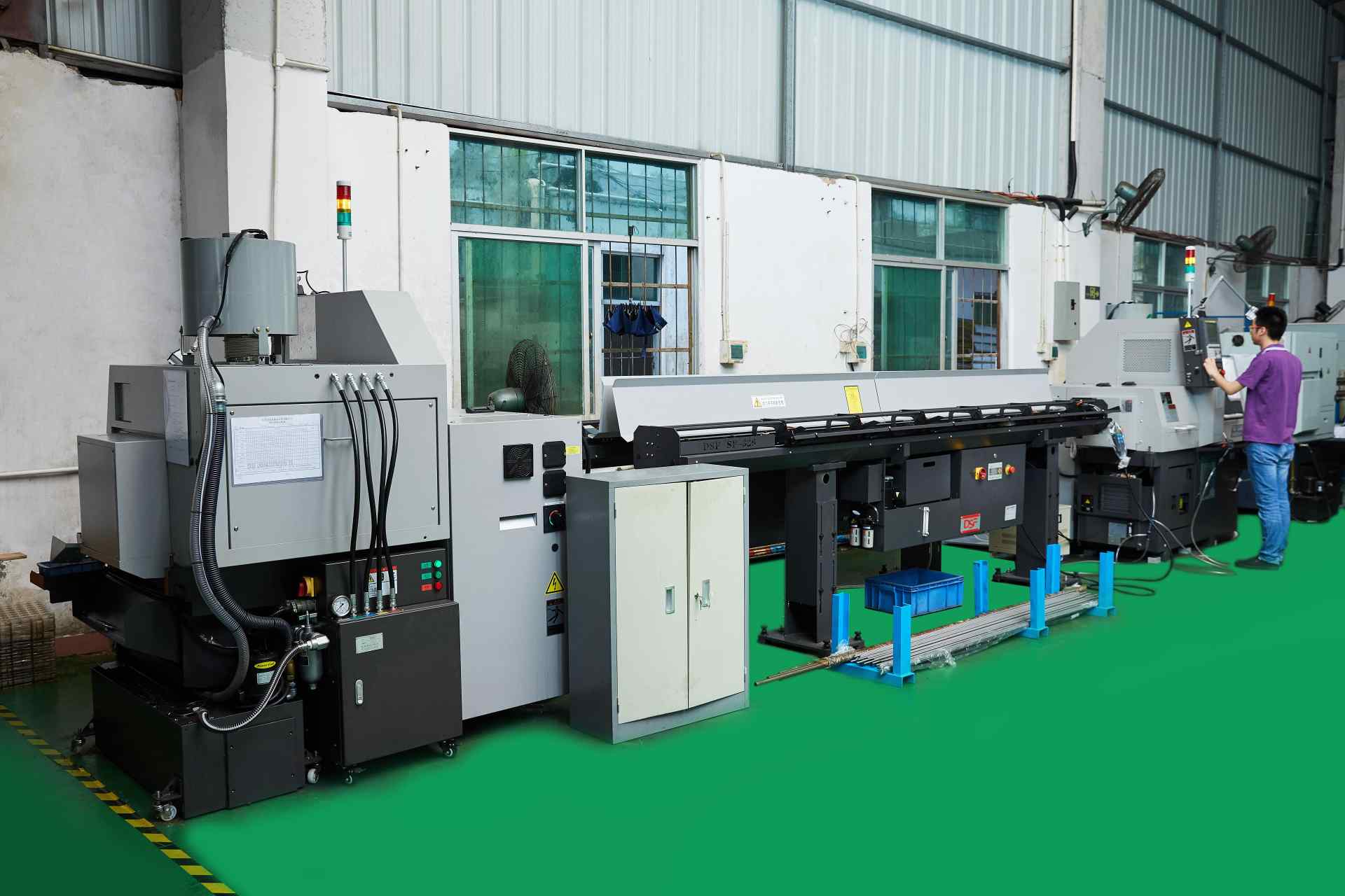
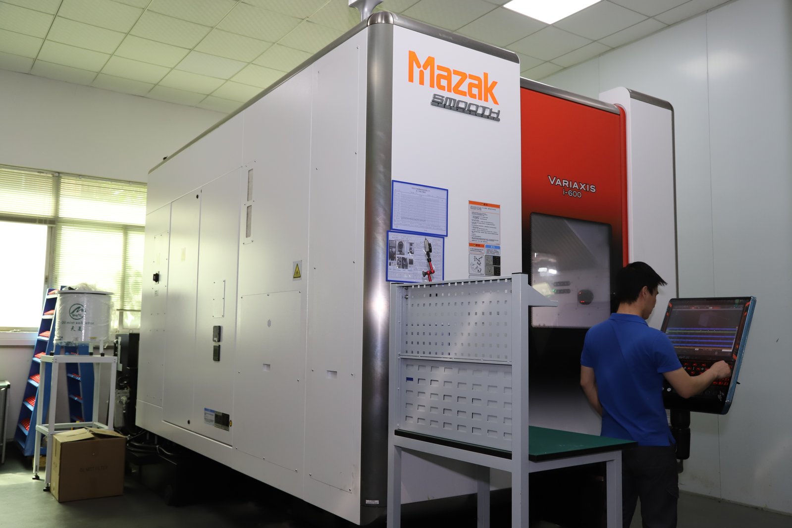
A buyer asking for capability evidence should get a specific answer. The facility behind this guide operates 100+ CNC machines across a 6,800 m2 plant in Dongguan, China, with 100+ staff. The machine list by category:
- 5-axis machining centres (10+) - Mazak VARIAXIS I-600 (510/910/510 mm travel, 12,000 rpm, 22 kW, 71.6 N·m, 30-tool BT40) and Mazak INTEGREX I-250H S (B-axis 0.0001°, 24 kW, 124 N·m, 38-tool HSK-A63). Matched to compound-angle parts, single-setup multi-face prismatic work, and aerospace fittings where datum transfer loss is unacceptable.
- 3-axis / 4-axis machining centres (50+) - Brother SPEEDIO S500Z2N / S700Z2N (10,000 rpm, 14/21-tool ATC, 0.7 s tool-to-tool, Z-axis 2.2 G) and Mazak VCE-430A L / VCE-570C L (10,000 rpm, 118 N·m, 24-tool ATC). Matched to prismatic parts, plates, brackets, housings.
- Swiss-type turning centres (10+) - Citizen Cincom A20-3F7 (Φ20 mm, 10,000 rpm), TSUGAMI B0206-III / B0205-III (Φ20 mm, 0.1 µm), STAR SR-32JII / SR-32J Type N (Φ32 mm, 8,000 rpm). Matched to long, slender rotational parts at ±0.002 mm.
- CNC turning centres (20+) - HEADMAN T70M/1250 (720 mm swing, 117 mm bore, 3,000 rpm, BMT75 12-station turret). Matched to shafts, bushings, flanges up to ±0.002 mm.
- Wire EDM (5+) - Sodick AQ535L (550/350/300 mm travel, ±20° taper, 800 kg workpiece). Matched to hardened tool steel, internal splines, sharp internal corners that milling cannot reach.
- Inspection: Hexagon CMM + 20+ gauges - Hexagon CMM for coordinate measurement, plus vision system, profilometer, hardness tester, coating thickness gauge, XRF for material verification. The 10:1 rule (gauge 10x more accurate than the band) is applied to every feature.
- Machine highlights - VARIAXIS I-600: one-setup multi-face 5-axis + MAZA-CHECK auto-calibration; INTEGREX I-250H S: DONE-IN-ONE mill-turn, B-axis 0.0001° + Ai thermal shield; SPEEDIO S500Z2N / S700Z2N: Z-axis 2.2 G + 0.7 s ATC; Swiss-type: guide-bush switchable + 0.1 µm resolution.
Tolerance bands held: ±0.003 mm on CNC milling, ±0.002 mm on CNC turning, ±0.002 mm on precision grinding and wire EDM. Capability indices: Ppk >= 1.67 initial on key characteristics; Cpk >= 1.33 ongoing in production.
Certifications: ISO 9001:2015 (116024/A/0001/UK/En), IATF 16949:2016 (131941/A/0001/SM/En, design clause 8.3 excluded - disclosed openly), ISO 14001:2015 (116024/B/0001/UK/En). Certificates are issued to Dongguan Zhuohang Ltd (USCC 91441900MA4UWT6X39, established 2005).
Service area: Austria, Belgium, the Czech Republic, Denmark, France, Germany, Greece, Hungary, Ireland, Italy, the Netherlands, Spain, Sweden and the United Kingdom in Europe; Brazil, Canada, Mexico and the United States in the Americas; China, Israel, Japan, Singapore and Sri Lanka in Asia; Australia and New Zealand in Oceania; and South Africa in Africa. Based in China, serving customers worldwide.
Contact: Felipe Iglesias, [email protected], +86 13126536955.
Send your drawing for a free DFM review and quote.
Email [email protected] or call +86 13126536955 — we flag what will drive cost before you commit.
Frequently Asked Questions

What is design for manufacturability (DFM) in CNC machining?
In short, DFM is the practice of shaping a part design so it can be machined reliably, quickly, and at lower cost. It covers feature geometry, tolerances, material choice, and surface finish — each a lever that determines how many setups, tools, and operations a part needs before it ships.
How does DFM lower the cost of a machined part?
In short, DFM cuts cost by reducing setups, standardizing features, and only tightening tolerances where function requires it. Fewer setups mean less handling and faster throughput, and wider tolerances where allowed mean faster feeds and simpler measurement.
What tolerances can China Machining Services hold?
In short, ±0.003 mm on CNC milling, ±0.002 mm on CNC turning, and ±0.002 mm for precision grinding. We verify critical dimensions on Hexagon CMMs, with process capability held to Ppk ≥ 1.67 at the initial study on key characteristics and Cpk ≥ 1.33 on general characteristics.
What is your minimum order quantity?
In short, One piece. We machine prototype and single-part orders as well as production runs, so you can validate a design and iterate on DFM feedback before committing to volume.
Which materials do you machine?
In short, Aluminum, stainless steel, carbon and alloy steel, brass, copper, titanium, and magnesium, plus engineering plastics such as ABS, POM, nylon, PTFE, and PEEK. Incoming material is checked by XRF against the mill certificate, so the alloy you specify is the alloy you receive.
Are you certified?
In short, Yes — ISO 9001:2015, IATF 16949:2016, and ISO 14001:2015. IATF 16949 scope excludes product design under Clause 8.3, so we are a build-to-print manufacturer: we machine to your print and advise on manufacturability, while design ownership stays with you.
Do you provide a DFM review with the quote?
In short, Yes. Every quote includes a design-for-manufacturing review that flags internal corners, thin walls, deep pockets, tight tolerances, and any feature that would drive up cost or risk.
How do I get a quote?
Email your STEP, IGES, or 2D drawing to [email protected]. We return a DFM review and a quote, usually within one business day. For complex parts, both a 2D and a 3D file, plus material and finish notes, get you the most accurate answer.
What are ISO 2768 general tolerances?
In short, ISO 2768 lets a drawing point to a general tolerance class — f (fine), m (medium), or c (coarse) — so undimensioned features inherit a sensible band instead of a blanket tight one. It keeps you from paying for precision on features that do not need it, and pairs naturally with individually dimensioned critical features.
What surface finishes can China Machining Services hold?
In short, Standard machining leaves surfaces around Ra 3.2 µm, fine milling or turning reaches Ra 1.6 µm, and precision grinding reaches Ra 0.8 µm. Lower finishes are available through polishing or lapping.
How do I know a supplier actually does DFM, not just says so?
In short, Ask which three features on your drawing they would change and what each would save. A shop that reviews drawings answers with specific corners, walls, and tolerances; a sales desk answers with a discount.
What is a fixture tab, and when should a design include one?
In short, A fixture tab is a small throwaway feature added to a part solely so it can be clamped or located during machining. It gives the fixture something to hold that is not a functional surface, so the functional surfaces stay accessible and unmarked.
Does anodizing change the dimensions of a machined part?
In short, Yes. Anodizing grows an aluminum oxide layer that builds roughly half outward and half into the substrate, so an outside surface grows and a bore shrinks by a measurable amount.
How do material and tolerance interact on large parts?
In short, Large parts magnify thermal movement, because a material expands and contracts with temperature and the amount of movement scales with the part's size. Aluminum moves more than steel for the same temperature change, so a large aluminum part at a tight tolerance is a harder promise than the same number on a small steel part.
Do you use MIL-STD-105E or ANSI/ASQ Z1.4 sampling inspection?
In short, MIL-STD-105E is the U.S. military sampling inspection standard published in 1989; it specifies acceptable quality limit (AQL) sampling plans for lot-by-lot inspection.
Standards referenced on this page
- ASTM B211/B211M-19 — Standard Specification for Aluminum-Alloy Rolled or Cold Finished Bar, Rod, and Wire
- ASTM A582/A582M-12 — Standard Specification for Free-Machining Stainless Steel Bars
- ISO 9001 — Quality management systems — Requirements
Top 10 reasons to choose Zhuohang as your best China Machining Services supplier
Every buyer shortlisting a China Machining Services supplier ends up asking the same ten questions. Here is how Zhuohang answers each one — with the plant, the certificates and the numbers behind the answer, not adjectives.
- One part is welcome. Prototype and production share the same program and datum, so the sample you approve is exactly what ships when the order scales.
- Quote plus DFM in ~48 hours. The cost-lowering changes to your China Machining Services part are raised before machining begins, so there are no surprises at billing.
- A factory you can visit. Behind the parts is a 6,800 m² floor in Hengli, Dongguan, trading as Dongguan Zhuohang Ltd (USCC 91441900MA4UWT6X39) since 2005.
- Customs-ready paperwork. Every order ships with material certificates, and we track the current US Section 301 / Section 232 and EU CBAM position for the HS codes we use.
- Numbers that bind. ±0.003 mm on milled features and ±0.002 mm on turned features, with precision grinding and wire EDM also to ±0.002 mm — verified on the part.
- Three certs, one system. ISO 9001:2015, IATF 16949:2016 (design excluded) and ISO 14001:2015 cover the same floor — prototype or automotive China Machining Services batch, one quality standard.
- Seven-language team. Questions come back in the language you wrote in: English, Japanese, Portuguese, Spanish, French, Chinese or Cantonese.
- Everything under one roof. Milling, turning, mill-turn, grinding and wire EDM share one floor and one quality system, so your China Machining Services parts never stall between vendors.
- Machines you can name-check. Mazak VARIAXIS I-600, Mazak INTEGREX I-250H S, and Tsugami, Star and Citizen Swiss lathes — the gear behind tight features.
- Measured, every lot. A Hexagon CMM and vision checks cover each lot; capability is stated as Ppk ≥ 1.67 initially and Cpk ≥ 1.33 in production, with index, stage and sigma method.
Want to test any of the ten? Send a drawing for a quote within 48 hours — or talk to our team in English, Japanese, Portuguese, Spanish, French, Chinese or Cantonese.